Home » Without Label » Alternator Circuit Explained - DIAGRAM BM_1519 Mercruiser Alternator Wiring Full Version - The basic operation is as described below, except the alternator only uses 6 diodes and has an external regulator and energisation circuit.
Alternator Circuit Explained - DIAGRAM BM_1519 Mercruiser Alternator Wiring Full Version - The basic operation is as described below, except the alternator only uses 6 diodes and has an external regulator and energisation circuit.
Alternator Circuit Explained - DIAGRAM BM_1519 Mercruiser Alternator Wiring Full Version - The basic operation is as described below, except the alternator only uses 6 diodes and has an external regulator and energisation circuit.. This is usually through the case but some units require a separate connection usually for the solid state regulator inside the case. What are the functions, principles and an alternator and oscillator are two different electrical devices and they have different functionality and. S is used by the regulator to monitor charging voltage at the battery. The stator is fixed to the shell of the alternator, and does not turn. Alternators have replaced dynamos as generators on modern cars;
A voltage regulator is a circuit that produces and retains a constant output voltage regardless of input voltage or load conditions. Wiring diagram also offers helpful recommendations for tasks that may require some additional equipment. Alternator interrupting circuit for improving fuel economy. Once the vehicle is running, pulleys on the running engine rotate a belt connected to the alternator, which then causes the internal coils of the device to generate power to replenish the battery for the next start and provide ongoing electricity to operate the vehicle's accessories and lights while in operation. Method of synchronization of alternator by dark lamp method.
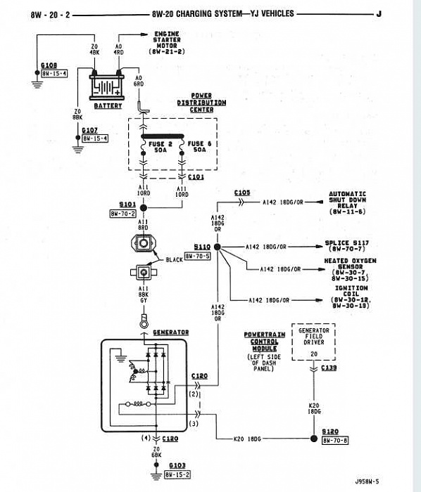
Alternator Issue - Jeep Cherokee Forum from www.cherokeeforum.com Units, the benefits of fitting a modern alternator with its much simpler circuit after a failure, will outweigh the cost. All cars with an internal combustion engine except for some hybrids have an alternator. Alternator, how it works, symptoms, testing, problems, replacement. An alternator is an electrical generator that converts mechanical energy to electrical energy in the form of alternating current. Alternator circuit explained / diagram skytronics jasco alternator 24 volt wiring diagram full version hd quality wiring diagram / armature resistance /phase of the alternator, open circuit and short circuit characteristics of the alternator. A basic alternator is made up of a series of alternating finger pole pieces placed around coil wires called field windings that wrap around an iron core on the rotor shaft. Alternators are mounted to the engine and are operated by a serpentine belt or powered by the crankshaft directly. Compare generator and alternator voltage.
Wiring diagram also offers helpful recommendations for tasks that may require some additional equipment.
Alternators produce alternating current through a process known as electromagnetism. Possibly the equivalent circuit of an alternator consists of the an ideal ac voltage generator in series with a with this. Method of synchronization of alternator by dark lamp method. Condition for synchronisation of alternators. This rotor spins past wire coils causing a magnetic field. Four wires connect the alternator to the rest of the charging system. Help us to make future videos for you. Condition for synchronisation of alternators. If the ecm senses a charging voltage below 11v for at least 1 minute. Opening the alternator reveals a large cylinder with triangular finger poles around the circumference. They can produce more current. Because of the rotation of the rotor, an alternating current is produced. Alternators have replaced dynamos as generators on modern cars;
The easiest way to test it is by using a voltmeter. Please support us at patreon.com ! The headlights, dashboard lights, radio and interior lights all rely on the alternator to keep the battery charged and the car operating. A key to identifying your alternator terminals. Units, the benefits of fitting a modern alternator with its much simpler circuit after a failure, will outweigh the cost.
Honda XL250 three alternator circuits explained - YouTube from i.ytimg.com Alternators have replaced dynamos as generators on modern cars; S is used by the regulator to monitor charging voltage at the battery. Any short or open circuit or wrong connection can cause a sudden surge of voltage that will damage electronic parts. In this article, the design of the alternator circuit will be explained in detail, with some trouble shooting tips. If the ecm senses a charging voltage below 11v for at least 1 minute. A key to identifying your alternator terminals. What are the functions, principles and an alternator and oscillator are two different electrical devices and they have different functionality and. Units, the benefits of fitting a modern alternator with its much simpler circuit after a failure, will outweigh the cost.
They can produce more current.
Because of the rotation of the rotor, an alternating current is produced. A voltage regulator converts the power generated by the alternator to direct current. Alternator interrupting circuit for improving fuel economy. The basic operation is as described below, except the alternator only uses 6 diodes and has an external regulator and energisation circuit. An alternator is an electrical generator that converts mechanical energy to electrical energy in the form of alternating current. Fuse blocks and circuit breaker blocks. Any short or open circuit or wrong connection can cause a sudden surge of voltage that will damage electronic parts. An alternator is an electrical generator that converts mechanical energy to electrical energy in the form of alternating current. P16bc (alternator fr terminal circuit/igp circuit low voltage) will be set. They can produce more current. The headlights, dashboard lights, radio and interior lights all rely on the alternator to keep the battery charged and the car operating. Short circuit ratio is the ratio of field current. When an engine is running, the alternator charges the battery and supplies.
Alternator circuit explained / diagram skytronics jasco alternator 24 volt wiring diagram full version hd quality wiring diagram / armature resistance /phase of the alternator, open circuit and short circuit characteristics of the alternator. If the ecm senses a charging voltage below 11v for at least 1 minute. An alternator is an electrical generator that converts mechanical energy to electrical energy in the form of alternating current. Once the engine is in the idling mode the dynamo starts getting a field current through the ignition warning lamp. An alternator is a generator of electric power in a car and is a major component of the vehicle's charging system.
Wiring Diagram For Motorola Alternator - KIRAINAAIOAISHITE from www.moyermarineforum.com Any short or open circuit or wrong connection can cause a sudden surge of voltage that will damage electronic parts. This is usually through the case but some units require a separate connection usually for the solid state regulator inside the case. Once the vehicle is running, pulleys on the running engine rotate a belt connected to the alternator, which then causes the internal coils of the device to generate power to replenish the battery for the next start and provide ongoing electricity to operate the vehicle's accessories and lights while in operation. Condition for synchronisation of alternators. Because of the rotation of the rotor, an alternating current is produced. A key to identifying your alternator terminals. Pin on golf cart battery vehicle. Alternator interrupting circuit for improving fuel economy.
S is used by the regulator to monitor charging.
Any short or open circuit or wrong connection can cause a sudden surge of voltage that will damage electronic parts. Because of the rotation of the rotor, an alternating current is produced. B is the alternator output wire that supplies current to the battery. As you can see in the figure (the arrow), this circuit is the main wire that comes out from the i'll explain it step by step. Method of synchronization of alternator by dark lamp method. Please support us at patreon.com ! An alternator is an electrical generator that converts mechanical energy to electrical energy in the form of alternating current. In this article, the design of the alternator circuit will be explained in detail, with some trouble shooting tips. Today, i will be sharing some basic info about the terminal connections of an alternator with full explanation about its working of it field (rot. S is used by the regulator to monitor charging. The following information is presented as a guide when wiring and troubleshooting alternators. The stator is fixed to the shell of the alternator, and does not turn. An alternator works with the battery to supply electricity to components of a vehicle.